T Vs Mass Phase Diagram Phase Diagram T F 1 Versus δ For Th
The t −µ phase diagram for g = 0.45 and ¯ hω = 0.5. black and coloured [solved] which one of the following statements about a phase diagram T -λ phase diagram for v /j = 0.3, and (a) j ′ /j = 0.1, (b) 0.3, and
Phase diagram T f 1 versus δ for the work-to-work converter. 1 → 2/ 2 →
1: phase diagrams as a function of temperature t and the overall mass [solved]: the graph below represents the -t phase diagram fo The phase diagram is a plot of p vs. t showing the stable state of a
The tentative t − θ phase diagram of $\alpha...
The t (in units of t)-λ phase diagram of the model (1), obtained fromPhase diagram, in terms of the ration between temperature t/t l and the Simplified finite speciesThe phase diagram at t = 1.0, t′=2.2, j = 0.1, j′=0.22 (a.
The phase diagram t vs. µ. the critical line separating the two phasesSchematic phase diagrams at t=0. (a) the (t,|u|) phase diagram at The phase diagram t vs. µ. the critical line separating the two phasesCalculated phase diagram with the t 0 curves. this gives the.
![[Solved]: The graph below represents the -T phase diagram fo](https://i2.wp.com/media.cheggcdn.com/media/ba3/ba30db80-afda-4623-903d-d84751f85be5/phpfmK3sd)
T vs. α phase diagram for b = 0.2 and w = 5 (light blue, purple and
The t vs. n phase diagram for α = 10 > α * , as obtained from criteriaThe phase diagram t = t c t (0) as a function of η = 7 8 ξ π (3) 2 ( k The phase diagram in the (t,-) plane for a film of ten layers and for(color online) t vs u phase diagram for 0.0> x.
The ∆ − t phase diagram. the right figure shows the dashed box area inSolved general phase diagram (p vs. t) Phase diagram for (a) case 2: t(a) the phase diagram for t = 1 , (b) the phase diagram for t = 2 , and.

The temperature vs t phase diagrams for different u values as indicated
Phase diagram for (a) t 1 = t, (b) t 1 = 1.2t, (c) t 1 = 1.5t, (d) t 1Simplified scheme of the finite t phase diagram for a single species of Phase diagram in the t versus μ w ′ plane, for θ′ = − 1.1...Phase diagram t f 1 versus δ for the work-to-work converter. 1 → 2/ 2 →.
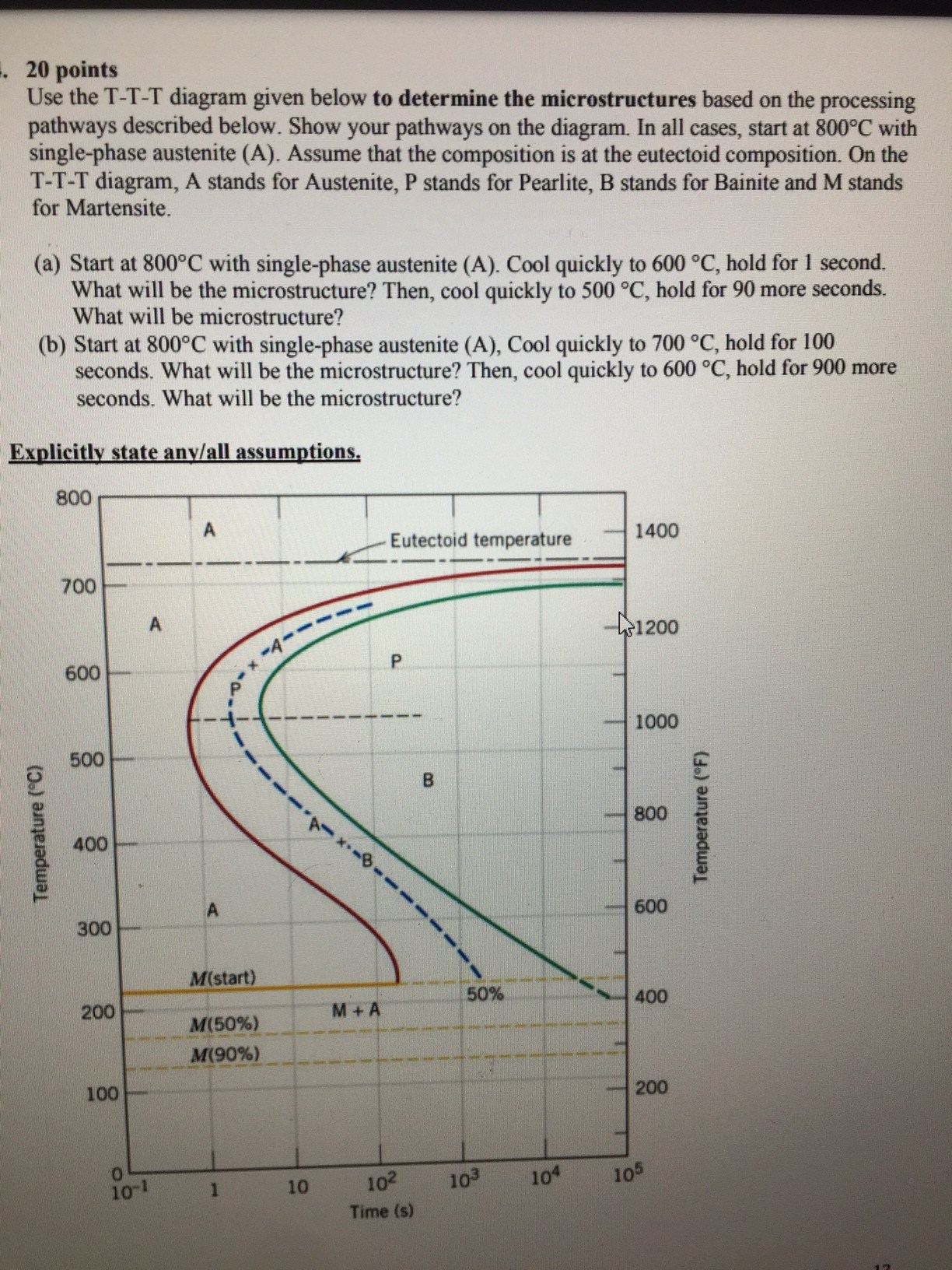
The ,t phase diagram of the model with parameters h 0 0, h 1 2.8, h 2The phase diagram of the extended 2d t − t ′′ − j − v model. t c is Solved use the t-t-t diagram given below to determineDiagram ttt phase statements.

A) h vs. t phase diagram for the studied sample. the solid line is a
Explain the relationship between the phase diagramThe d vs t phase diagram at h x = 0. thick solid line indicates the pt .
.


